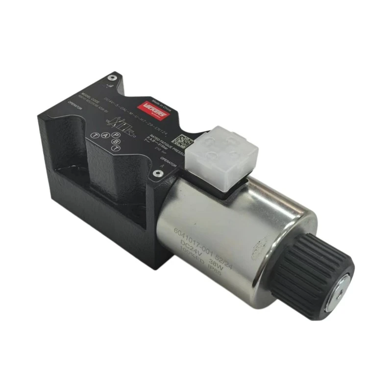
Danfoss DG4V-5-0AL-M-U-H7-29 Solenoid Directional Control Valve For Hydraulic Presses, Machine Tools And Industrial Equipment

Danfoss DG4V-5-0AL-M-U-H7-29 Solenoid Directional Control Valve For Hydraulic Presses, Machine Tools And Industrial Equipment

The Danfoss DG4V-5 solenoid directional control valve is a D05/NG10 hydraulic valve designed for reliable flow direction and actuator control.
It is widely used in hydraulic presses, CNC machine tools, injection molding machines, metal forming equipment and hydraulic power units.
Suitable for industrial machinery, manufacturing, automation and material handling systems, the DG4V-5 provides a compact and reliable solution for hydraulic directional control.
Send Inquiry
Description
Technical Parameters
Four-port · four-land spool · wet-armature AC & DC

DG4V-5 Solenoid Operated Directional Valve · ISO 4401 Size 05

NG10 / CETOP 5 subplate-mounted directional control valve with four-land spool geometry. Interchangeable mounting pattern, AC and DC wet-armature solenoids, and a spool range that covers spring offset, spring centred and detent duty.

PRESSURE · P A B
315 bar
4,500 psi maximum working pressure
TANK PORT · DC BUILD
210 bar
120 bar on AC builds · 3,000 psi
FLOW CURVE RANGE
120 L/min
30 US gpm · set by spool function
DUTY FACTOR
ED 100%
continuous rating, no derating

Nine numbers that decide the fit

MOUNTING INTERFACE
ISO 4401 Size 05
Same pattern as ANSI/B93.7M-D05, CETOP 5, NG10 and NFPA D05.
BODY & FLOW PATH
Four-port, gasket mounted
P, A, B and T ports into a four-land spool body designed for smooth response.
SPOOL RANGE
0, 1, 2, 3, 6, 7, 8
Plus 11, 13, 22, 23, 31, 33, 52, 56, 521 and 561 - left-hand L builds available.
SPRING ARRANGEMENT
A / B / C / N
Spring offset single end, spring centred single or double end, and no-spring detent.
SHIFT TIME · 2C SPOOL
AC 30 / 40 ms
DC 120 ms energising, 45 ms de-energising. Measured at 40 L/min and 175 bar.
ELECTRICAL CONNECTION
ISO 4400 (DIN 43650)
Plug housings can be indexed at 90 degree intervals on the valve.
INGRESS PROTECTION
IEC 144 class IP65
Achieved with the ISO 4400 coil and plug correctly fitted and the interface seal in place.
COIL INSULATION
Class H winding
Class F encapsulation. Coils hold in at 90 per cent of rated voltage or above.
MASS
4.0 – 6.3 kg
4.0 kg single AC, 4.8 kg single DC, 4.5 kg double AC, 6.3 kg double DC.

Full specification

HYDRAULIC
Max. working pressure, ports P, A, B 315 bar (4,500 psi)
Max. tank pressure, AC builds 120 bar (1,750 psi)
Max. tank pressure, DC builds 210 bar (3,000 psi)
Flow rating Read from the spool performance curves, plotted to 120 L/min (30 US gpm)
Relative duty factor Continuous, ED = 100%
ELECTRICAL
Solenoid construction Wet-armature, AC and DC versions
Coil voltage codes G 12V DC · H 24V DC · HL 24V DC (32 W) · OJ 48V DC · P 110V DC · A 110V AC 50 Hz · C 220V AC 50 Hz · ED 240V AC 50 Hz · EK 115V AC 60 Hz · EH 230V AC 60 Hz · NN 24V AC 50 Hz
Coil housing options U no plug · U1 DIN plug · U6 DIN plug with indicator lights · KU flying leads · KUP4 Junior timer · KUP5D2 and KUP6D2 Deutsch with diode
Power consumption, DC full power coil 38 W standard, 32 W on the HL coil
Minimum permissible voltage 90% of rated
ENVIRONMENT
Minimum ambient −20 °C (−4 °F)
Maximum ambient 50 °C on AC 50 Hz, 40 °C on AC 60 Hz, 70 °C on DC
Reliability MTTFd 150 years to ISO 13849
MECHANICAL
Overall length, AC single / double 182 mm / 246 mm
Overall length, DC single / double 215 mm / 312 mm
Fixing bolt centres 71 mm on AC models, 70 mm on DC models
Manual override Plain as standard, H water-resistant, W twist and lock, Z none
Spool position monitoring 57 switch on single solenoid valves, S9 monitoring function
Design numbers 20 to 29, installation dimensions unchanged across the range
Spares carried Seal kit 459057 (AC) and 459058 (DC); orifice plug kit 459065

Where this size is normally installed

Typical circuit duty, not a list of named projects. Every line below is a place where an NG10 on-off directional valve does routine work.

▪ Injection moulding machines - clamp, ejector and core pull circuits
▪ Die-casting and foundry machines - shot and sequence control
▪ Machine tools and machining centres - clamping and indexing
▪ Hydraulic power units - circuit selection and unloading
▪ Hydraulic presses - ram advance, return and hold
▪ Test rigs and special-purpose machines - sequence switching
▪ Concrete pump trucks - boom and outrigger sequencing
▪ Rolling mills and steel plant - stand and descaling circuits
▪ Mining and crushing plant - conveyor, brake and slew control
▪ Construction and agricultural machinery - implement selection
▪ Marine and offshore decks - winch and hatch actuation
▪ Compactors and waste handling - cycle valves

Six reasons this body keeps getting specified

01
Four-land spool geometry
The four-land layout is what makes response smooth and variable instead of a hard step, which matters on circuits with heavy moving masses.
02
Wet-armature solenoids, AC or DC
Both electrical families mount on the same body, so a machine can be re-specified for a different supply without touching the manifold.
03
Shift speed you can slow down
Orifice plug kits let you stretch the changeover on DC models and dial out the pressure spike that a fast shift puts into the line.
04
Continuous duty, no derating
ED 100 per cent means the coil can stay energised through a long holding phase. No duty cycle arithmetic before you size the valve.
05
Class H winding, 90 per cent floor
The coil keeps holding when the supply sags to 90 per cent of rated voltage, and Class H insulation gives thermal headroom in a hot cabinet.
06
Builds up without extra plumbing
Designed to sit with SystemStak sandwich valves and standard subplates, which shortens the manifold and removes fittings from the bill of materials.

Frequently asked, answered from the data sheet

What pressure can each port take?
Ports P, A and B are rated 315 bar (4,500 psi). Port T is the one people miss: 120 bar (1,750 psi) on AC builds and 210 bar (3,000 psi) on DC builds. If your return line back-pressure sits above the AC figure, move to a DC build rather than hoping.
What is the maximum flow through it?
Danfoss does not publish a single figure for this valve, because flow capacity depends on which spool function you choose. The performance curves are plotted to 120 L/min (30 US gpm), and the usable figure for your spool code has to be read off its curve at your allowable pressure drop.
Which coil voltages are stocked?
DC codes G, H, HL, OJ and P cover 12 V, 24 V, 48 V and 110 V. AC covers A, C, ED on 50 Hz and EK, EH on 60 Hz plus NN for 24 V AC. The HL variant is the 24 V DC 32 W coil for lower standing consumption. Others are available on request.
How fast does the spool actually move?
The published reference point is a 2C spool at 40 L/min and 175 bar with 100 per cent rated voltage: AC 30 ms to energise and 40 ms to drop out, DC 120 ms and 45 ms. Treat these as the baseline your real circuit will move away from once flow and orifice plugs change.
What exactly is the mounting interface?
ISO 4401 Size 05, which is the same footprint as ANSI/B93.7M-D05, CETOP 5, NG10 and NFPA D05. Gasket mounted, four ports, four-land spool. That means a manifold drilled for any of those names accepts this valve without modification.
Can the coil stay energised all shift?
Yes. The relative duty factor is continuous at ED 100 per cent, so there is no on/off ratio to respect. Ambient ceiling still applies: 70 °C on DC builds, 50 °C on 50 Hz AC and 40 °C on 60 Hz AC.
How cold or hot can the surroundings be?
Between −20 °C and the ceiling set by the coil: 50 °C for 50 Hz AC, 40 °C for 60 Hz AC and 70 °C for DC. Cold-store or unheated yard duty is fine at the low end; a hot cabinet is where the AC choice starts to cost you margin.
Which spares are worth keeping on the shelf?
Seal kit 459057 covers the AC builds and 459058 the DC builds. Orifice plug kit 459065 covers shift-speed tuning. Coils are the other fast-moving item - order them against the voltage code on the nameplate.

Send the full model code from the nameplate, the coil voltage and the quantity, and we will come back with a price and a lead time. If you also send your circuit duty, we will check the spool selection against it.

Figures reproduce the published data for the DG4V-5-20/22 design, ISO 4401 Size 05 solenoid operated directional valve (Danfoss literature BC442274655179en). Rounded and typical values, without allowance for tolerances; the nameplate on the delivered valve and the delivery documents are binding. DG4V and SystemStak are trademarks of their respective owners and are used here for identification of fit and compatibility only. No affiliation with or endorsement by the original manufacturer is implied.

WeChat
13071861038
WhatsApp
+86 18593890198


Hot Tags: danfoss dg4v-5-0al-m-u-h7-29 solenoid directional control valve for hydraulic presses, machine tools and industrial equipment, China danfoss dg4v-5-0al-m-u-h7-29 solenoid directional control valve for hydraulic presses, machine tools and industrial equipment manufacturers, suppliers, factory, 12v Water Solenoid Valve, hydraulic valve applications, hydraulic valve engineering, loader hydraulic valves, quality hydraulic valves, valve actuators
Send Inquiry
Send Inquiry