FLUID POWER CONTROL
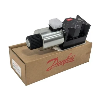
DG4V-3 Hydraulic Directional Valve
Understanding flow switching, actuator response and system compatibility.
How Directional Control Works
A solenoid-operated directional valve uses an electrical command to shift its spool between designed positions. Each position establishes a defined hydraulic flow path. The resulting actuator movement depends on the spool symbol, supply arrangement and connected components.
Electrical Command
Control signal energizes the applicable coil.
Spool Position
The valve changes the available oil passages.
Actuator Response
The connected cylinder or motor responds to the circuit.
Illustrative functional sequence only. Actual port connections and neutral-state behavior must be confirmed from the hydraulic symbol for the selected valve.
System Components
- Hydraulic pump and fluid reservoir
- Directional control valve and manifold
- Hydraulic cylinder or motor
- Pressure relief and flow control components where required
- Electrical command and machine control circuit
Potential Applications
- Hydraulic power units
- Industrial presses and forming machines
- Machine tool fixtures
- Factory automation equipment
- Hydraulic machinery maintenance
Troubleshooting Before Valve Replacement
Check system pressure, electrical command, spool configuration and flow path.
Check rated voltage, connector wiring and the condition of the coil.
Compare the model code, spool symbol, mounting interface and pressure limits.
Technical FAQ
No. The pump supplies hydraulic flow; the directional valve controls its path.
No. Neutral and energized flow paths depend on the selected spool design.
Only after hydraulic, electrical and mechanical compatibility have been verified.
Incorrect voltage can prevent reliable operation or damage electrical components.
Possible causes include insufficient flow, pressure loss, contamination or other circuit faults.
Yes. Contamination can interfere with spool movement and hydraulic component performance.
Use the exact model data sheet and confirm all relevant port pressure limits.
Record the nameplate code and photograph the valve, electrical connector and mounting face.
A verified part number and hydraulic symbol are the starting point for accurate sourcing and system compatibility.
Hot Tags: dg4v-3-2a-m-u-d6-60 hydraulic directional valve for industrial automation systems, China dg4v-3-2a-m-u-d6-60 hydraulic directional valve for industrial automation systems manufacturers, suppliers, factory